Export Data to MATLAB
Use a To Workspace Block
This section explains how to send data from a Simulink® model to the MATLAB® workspace so you can analyze the results of simulations in greater detail.
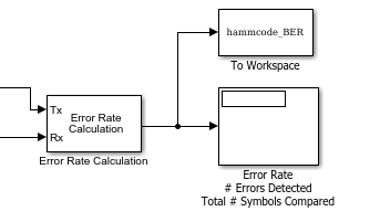
You can use a To Workspace (Simulink) block to send data to the MATLAB workspace as a vector. For example, you can send the error rate data from the Hamming code model, described in the section Reducing the Error Rate Using a Hamming Code. To insert a To Workspace (Simulink) block into the model, follow these steps:
To add a To Workspace (Simulink) block, begin typing the name 'to workspace' in the model window and select the To Workspace block. Connect it as shown.
Tip
Select the To Workspace block from the DSP System Toolbox™ / Sinks sublibrary. For more information, see To Workspace Block Configuration for Communications System Simulations.
Configure the To Workspace Block
To configure the To Workspace (Simulink) block, follow these steps:
Double-click the block to display its dialog box.
Type
hammcode_BERin the Variable name field.Type
1in the Limit data points to last field. This limits the output vector to the values at the final time step of the simulation.Ensure the Save format is set to
Array.Click OK.
When you run a simulation, the model sends the output of the Error Rate Calculation
block to the workspace as a vector of size 3, called hamming_BER. The
entries of this vector are the same as those shown by the Error Rate Display block.
View Error Rate Data in Workspace
After running a simulation, you can view the output of the To Workspace (Simulink) block by typing the following commands at the MATLAB prompt:
format short e
hammcode_BER
The vector output is the following:
hammcode_BER =
5.4066e-003  1.0000e+002  1.8496e+004
The command format short e displays the entries of the vector in
exponential form. The entries are as follows:
The first entry is the error rate.
The second entry is the total number of errors.
The third entry is the total number of comparisons made.
Send Signal and Error Data to Workspace
To analyze the error-correction performance of the Hamming code, send the transmitted signal, the received signal, and the error vectors, created by the Binary Symmetric Channel block, to the workspace. An example of this is shown in the following figure.
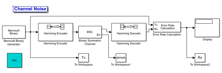
Assemble blocks to build this model.
Double-click the Binary Symmetric Channel block to open its dialog box, and select Output error vector. This creates an output port for the error data.
Move blocks to make room so that you can insert Hamming Encoder and Hamming Decoder blocks. To find them, start typing
Hammingin the model window. Select them from the options presented. These Hamming Encoder and Hamming Decoder blocks are in the Communications Toolbox™/Error Detection and Correction /Block sublibrary.Add three To Workspace (Simulink) blocks into the model window and connect them as shown in the preceding figure.
Tip
Select the To Workspace block from the DSP System Toolbox / Sinks sublibrary. For more information, see To Workspace Block Configuration for Communications System Simulations.
Double-click the left To Workspace (Simulink) block.
Set the Variable name parameter to
Tx. The block sends the transmitted signal to the workspace as an array calledTx.To save each frame as a separate column in the
Txarray, set the Save 2-D signals as parameter to3-D array (concatenate along third dimension).Click OK.
Double-click the middle To Workspace (Simulink) block:
Set the Variable name parameter to
errors.To save each frame as a separate column in the
errorsarray, set the Save 2-D signals as parameter to3-D array (concatenate along third dimension).Click OK.
Double-click the right To Workspace (Simulink) block:
Set the Variable name parameter to
Rx.To save each frame as a separate column in the
Rxarray, set the Save 2-D signals as parameter to3-D array (concatenate along third dimension).Click OK.
View Signal and Error Data in Workspace
After running a simulation, you can display individual frames of data. For example, to
display the tenth frame of Tx, at the MATLAB prompt type
Tx(:,:,10)
This returns a column vector of length 4, corresponding to the length of a message word. Signals are typically quite large. So, typing the signal name by itself and displaying the entire transmitted signal is not of interest.
To display the corresponding frame of errors, type
errors(:,:,10)
This returns a column vector of length 7, corresponding to the length of a codeword.
To display frames 1 through 5 of the transmitted signal, type
Tx(:,:,1:5)
Analyze Signal and Error Data
You can use MATLAB to analyze the data from a simulation. For example, to identify the differences between the transmitted and received signals, type
diffs = Tx ~= Rx;
The vector diffs is the XOR of the vectors Tx and
Rx. A 1 in diffs indicates that
Tx and Rx differ at that position.
You can determine the indices of frames corresponding to message words that are incorrectly decoded with the following MATLAB command:
error_indices = find(diffs);
The vector error_indices records the indices where
Tx and Rx differ. To view the first incorrectly
decoded word, type
Tx(:,:,error_indices(1))
To view the corresponding frame of errors, type
errors(:,:,error_indices(1))
Analyze this data to determine the error patterns that lead to incorrect decoding.
You can also select a web site from the following list:
Americas
- América Latina (Español)
- Canada (English)
- United States (English)
Europe
- Belgium (English)
- Denmark (English)
- Deutschland (Deutsch)
- España (Español)
- Finland (English)
- France (Français)
- Ireland (English)
- Italia (Italiano)
- Luxembourg (English)
- Netherlands (English)
- Norway (English)
- Österreich (Deutsch)
- Portugal (English)
- Sweden (English)
- Switzerland
- United Kingdom (English)