Main Content

Double-Acting Hydraulic Cylinder

(To be removed) Hydraulic actuator exerting force in both directions

The Hydraulics (Isothermal) library will be removed in a future release. Use the Isothermal Liquid library instead. (since R2020a)

For more information on updating your models, see Upgrading Hydraulic Models to Use Isothermal Liquid Blocks.

  • Double-Acting Hydraulic Cylinder block

Libraries:
Simscape / Fluids / Hydraulics (Isothermal) / Hydraulic Cylinders

Description

The Double-Acting Hydraulic Cylinder block models a device that converts hydraulic energy into mechanical energy in the form of translational motion. Hydraulic fluid pumped under pressure into one of the two cylinder chambers forces the piston to move and exert force on the cylinder rod. Double-acting cylinders transfer force and motion in both directions.

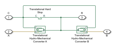
Connections R and C are mechanical translational conserving ports corresponding to the cylinder rod and cylinder clamping structure, respectively. Connections A and B are hydraulic conserving ports. Port A is connected to converter A and port B is connected to converter B.

The energy through hydraulic port A or B is directed to the appropriate Translational Hydro-Mechanical Converter block. The converter transforms hydraulic energy into mechanical energy and accounts for the fluid compressibility in the cylinder chamber. The rod motion is limited with the mechanical Translational Hard Stop block in such a way that the rod can travel only between cylinder caps.

Displacement

The piston displacement is measured as the position at port R relative to port C. The Cylinder orientation identifies the direction of piston displacement. The piston displacement is neutral, or 0, when the chamber A volume is equal to the chamber dead volume. When displacement is received as an input, ensure that the derivative of the position is equal to the piston velocity. This is automatically the case when the input is received from a Translational Multibody Interface block connection to a Simscape Multibody joint.

Composite Structure

The model of the cylinder is built of Simscape™ Foundation library blocks. The schematic diagram of the model is shown below.

Assumptions and Limitations

  • No leakage, internal or external, is taken into account.

  • No loading on piston rod, such as inertia, friction, spring, and so on, is taken into account. If necessary, you can easily add them by connecting an appropriate building block to cylinder port R.

Ports

Input

expand all

Piston displacement from cap A, received as a physical signal from a Simscape Multibody™ block.

Dependencies

To enable this port, set the Piston displacement from cap A parameter to Provide input signal from Multibody joint.

Conserving

expand all

Hydraulic conserving port associated with the cylinder chamber A.

Hydraulic conserving port associated with the cylinder chamber B.

Mechanical translational conserving port associated with the cylinder rod.

Mechanical translational conserving port associated with the cylinder clamping structure.

Parameters

expand all

Basic Parameters

Chamber B effective piston area.

Piston maximum travel between caps.

Fluid volume in chamber A that remains in the chamber after the rod is fully retracted.

Fluid volume in chamber B that remains in the chamber after the rod is fully extended.

Specific heat ratio used in compressibility calculations. This parameter is equivalent to the Specific heat ratio parameter of the Translational Hydro-Mechanical Converter block.

Specifies cylinder orientation with respect to the globally assigned positive direction. The cylinder can be installed in two different ways, depending upon whether it exerts force in the positive or in the negative direction when pressure is applied at its inlet. If pressure applied at port A exerts force in negative direction, set the parameter to Pressure at A causes negative displacement of R relative to C

Hard Stop Properties

Specifies the elastic property of colliding bodies for the Translational Hard Stop block. The greater the value of the parameter, the less the bodies penetrate into each other, the more rigid the impact becomes. Lesser value of the parameter makes contact softer, but generally improves convergence and computational efficiency.

Specifies dissipating property of colliding bodies for the Translational Hard Stop block. At zero damping, the impact is close to an absolutely elastic one. The greater the value of the parameter, the more energy dissipates during an interaction. Keep in mind that damping affects slider motion as long as the slider is in contact with the stop, including the period when slider is pulled back from the contact. For computational efficiency and convergence reasons, it is recommended that you assign a nonzero value to this parameter.

Modeling approach for hard stops. Options include:

  • Stiffness and damping applied smoothly through transition region (default) — Scale the magnitude of the contact force from zero to its full value over a specified transition length. The scaling is polynomial in nature. The polynomial scaling function is numerically smooth and it produces no zero crossings of any kind.

  • Full stiffness and damping applied at bounds, undamped rebound — Apply the full value of the calculated contact force when the hard-stop location is breached. The contact force is a mix of spring and damping forces during penetration and a spring force—without a damping component—during rebound. No smoothing is applied.

  • Full stiffness and damping applied at bounds, damped rebound — Apply the full value of the calculated contact force when the hard-stop location is breached. The contact force is a mix of spring and damping forces during both penetration and rebound. No smoothing is applied.

Region where the force is ramped up from zero to the full value. At the end of the transition region, the full stiffness and damping are applied.

Dependencies

To enable this parameter, set Hard stop model to Stiffness and damping applied smoothly through transition region, damped rebound.

Initial Conditions

Method for determining the piston position. Setting this parameter to Provide input signal from Multibody joint exposes the physical signal port p, which lets the block receive the piston position from a Simscape Multibody block.

The distance that the piston is extended at the beginning of simulation. You can set the piston position to any point within its stroke. The default value corresponds to the fully retracted position.

Dependencies

To enable this parameter, set Piston displacement from cap A to Calculate from velocity of port R relative to port C.

Pressure in the cylinder chamber A at the beginning of simulation.

Pressure in the cylinder chamber B at the beginning of simulation.

Extended Capabilities

C/C++ Code Generation
Generate C and C++ code using Simulink® Coder™.

Version History

Introduced in R2006a

collapse all

R2023a: To be removed

The Hydraulics (Isothermal) library will be removed in a future release. Use the Isothermal Liquid library instead.

For more information on updating your models, see Upgrading Hydraulic Models to Use Isothermal Liquid Blocks.