Double-Acting Rotary Actuator
(To be removed) Double-acting hydraulic rotary actuator
The Hydraulics (Isothermal) library will be removed in a future release. Use the Isothermal Liquid library instead. (since R2020a)
For more information on updating your models, see Upgrading Hydraulic Models to Use Isothermal Liquid Blocks.
Library
Hydraulic Cylinders

Description
The Double-Acting Rotary Actuator block models a double-acting hydraulic rotary actuator, which directly converts hydraulic energy into mechanical rotational energy without employing intermediary transmissions such as rack-and-pinion, sliding spline, chain, and so on. Hydraulic fluid pumped under pressure into one of the two actuator chambers forces the shaft to rotate and generate torque. Double-acting actuators generate torque and motion in both directions.
The model of the actuator is built of Simscape™ Foundation library blocks. The schematic diagram of the model is shown below.
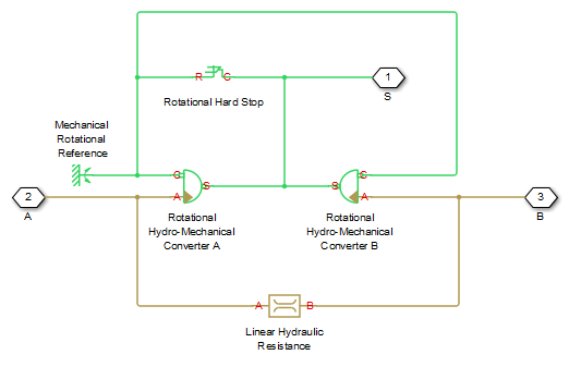
The blocks in the diagram perform the following functions:
| Rotational Hydro-Mechanical Converter A | Converts hydraulics energy into mechanical rotational energy when fluid is pumped into actuator chamber A, while accounting for fluid compressibility. |
| Rotational Hydro-Mechanical Converter B | Converts hydraulics energy into mechanical rotational energy when fluid is pumped into actuator chamber B, while accounting for fluid compressibility. |
| Rotational Hard Stop | Imposes limits on shaft rotation. |
| Linear Hydraulic Resistance | Accounts for leakages. |
Connections A and B are hydraulic conserving ports. Port A is connected to chamber A and port B is connected to chamber B. Connection S is a mechanical rotational conserving port associated with the actuator shaft.
The block directionality is adjustable and can be controlled with the Actuator orientation parameter.
Basic Assumptions and Limitations
No loading, such as inertia, friction, spring, and so on, is taken into account. If necessary, you can easily add them by connecting an appropriate building block to port S.
Parameters
- Actuator displacement
Effective displacement of the actuator. The default value is
4.5e-5m^3/rad.- Shaft stroke
Shaft maximum travel between stops. The default value is
5.1rad.- Shaft initial angle
The position of the shaft at the beginning of simulation. You can set the shaft position to any angle within its stroke. The default value is
0, which corresponds to the shaft position at the very beginning of the stroke.- Dead volume A
Fluid volume in chamber A that remains in the chamber when the shaft is positioned at the very beginning of the stroke. The default value is
1e-4m^3.- Dead volume B
Fluid volume in chamber B that remains in the chamber when the shaft is positioned at the end of the stroke. The default value is
1e-4m^3.- Leak coefficient
Leak coefficient for the Linear Hydraulic Resistance block. The default value is
1e-14(m^3/s)/Pa.- Specific heat ratio
Gas-specific heat ratio for the Hydraulic Piston Chamber block. The default value is
1.4.- Contact stiffness
Specifies the elastic property of colliding bodies for the Rotational Hard Stop block. The greater the value of the parameter, the less the bodies penetrate into each other, the more rigid the impact becomes. Lesser value of the parameter makes contact softer, but generally improves convergence and computational efficiency. The default value is
1e6N*m/rad.- Contact damping
Specifies dissipating property of colliding bodies for the Rotational Hard Stop block. At zero damping, the impact is close to an absolutely elastic one. The greater the value of the parameter, the more energy dissipates during an interaction. Keep in mind that damping affects slider motion as long as the slider is in contact with the stop, including the period when slider is pulled back from the contact. For computational efficiency and convergence reasons, MathWorks recommends that you assign a nonzero value to this parameter. The default value is 150 N*m/(rad/s).
- Hard stop model
Modeling approach for hard stops. Options include:
Stiffness and damping applied smoothly through transition
                    region
(default) — Scale the magnitude of the contact force from zero to its full value over a specified transition length. The scaling is polynomial in nature. The polynomial scaling function is numerically smooth and it produces no zero crossings of any kind.Full stiffness and damping applied at bounds, undamped rebound— Apply the full value of the calculated contact force when the hard-stop location is breached. The contact force is a mix of spring and damping forces during penetration and a spring force—without a damping component—during rebound. No smoothing is applied.Full stiffness and damping applied at bounds, damped rebound— Apply the full value of the calculated contact force when the hard-stop location is breached. The contact force is a mix of spring and damping forces during both penetration and rebound. No smoothing is applied. This is the hard-stop model used in previous releases.
- Transition region
Distance below which scaling is applied to the hard-stop force. The contact force is zero when the distance to the hard stop is equal to the value specified here. It is at its full value when the distance to the hard stop is zero. The default value is 1
mm..- Actuator orientation
Specifies actuator orientation with respect to the globally assigned positive direction. The actuator can be installed in two different ways, depending upon whether it generates torque in the positive or in the negative direction when pressure is applied at its inlet. If pressure applied at port A generates torque in the negative direction, set the parameter to
Acts in negative direction. The default value isActs in positive direction.
Global Parameters
Parameter determined by the type of working fluid:
Fluid bulk modulus
Use the Hydraulic Fluid block or the Custom Hydraulic Fluid block to specify the fluid properties.
Ports
The block has the following ports:
AHydraulic conserving port associated with the actuator chamber A.
BHydraulic conserving port associated with the actuator chamber B.
SMechanical rotational conserving port associated with the actuator shaft.
Extended Capabilities
Version History
Introduced in R2007aYou can also select a web site from the following list:
Americas
- América Latina (Español)
- Canada (English)
- United States (English)
Europe
- Belgium (English)
- Denmark (English)
- Deutschland (Deutsch)
- España (Español)
- Finland (English)
- France (Français)
- Ireland (English)
- Italia (Italiano)
- Luxembourg (English)
- Netherlands (English)
- Norway (English)
- Österreich (Deutsch)
- Portugal (English)
- Sweden (English)
- Switzerland
- United Kingdom (English)